V-Strom Symtec heated grip install
In general, there are two ways to keep your hands warm using the electric current produced by a motorcycle. Heated gloves and heated handle grips both have pros and cons. I chose heated grips because I only have one motorcycle at this time.
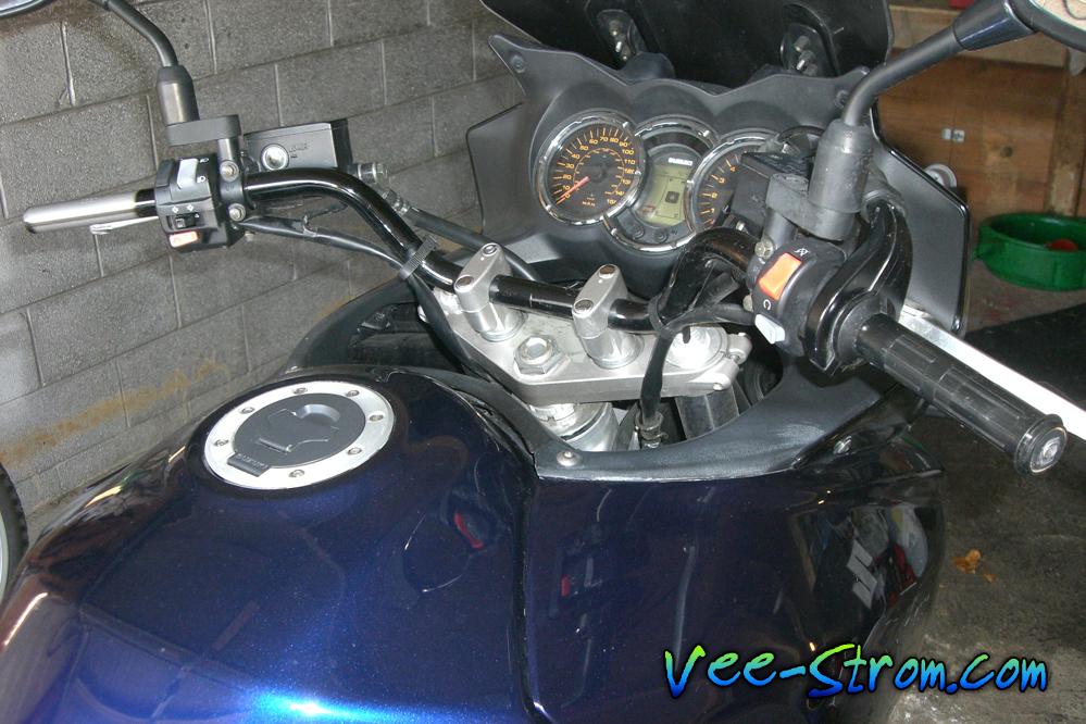
There are two types of heated grips. Some kits replace the entire rubber grip, while others consist of heating elements that can be placed beneath any rubber hand grip. This tutorial demonstrates how to install the latter type, manufactured by Symtec, beneath the original rubber grips on a 2004 V-Strom 1000.
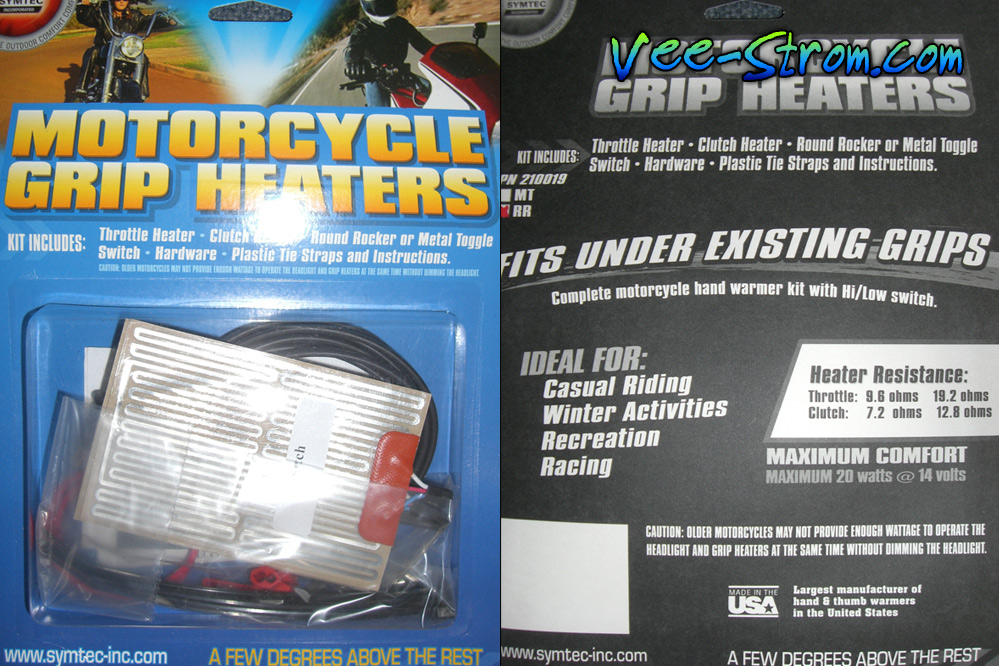
Symtec makes two types of grip heating element kits. The motorcycle grip heaters (less than 40$ on Amazon HANDLEBARS HEATER KT – Symtec –, a few dollars more with rocker style switch (part 17-9535) at cycle-parts.com) deliver an unbalanced amount of heat between the left and right sides. A plastic tube surrounds the throttle hand grip, while the clutch hand grip covers the bare metal handlebar tube. This difference affects the amount of heat each hand grip conducts. Symtec also makes an ATV grip heater kit that produces the same amount of heat for either hand. Heat delivery can also be modified with a troller. Typically, these devices have a knob to adjust the amount of heat. I opted to install the simple high/low/off switch that came with the kit.
Parts & Tools
- Grip heaters kit
- Suzuki horn lead wire
- Wire strippers, crimpers
- Soldering iron, solder & flux
- Heat shrink wrap (optional)
- Heat gun (optional)
- Electrical tape
Installation concerns & challenges
-
Power source
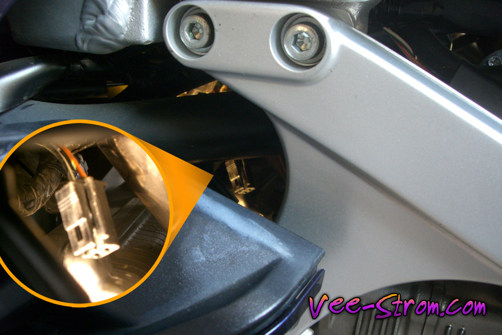
The V-Strom has a heated grip wire built into the wiring harness for the optional Suzuki hand warmers. The location of this wire is behind the radiator near the horn, and my picture will help you find the connector. With no other powered accessories, this is the obvious choice. There are a few ideal places for electricity on the bike, all of which are described in John’s V-Strom Wiring 101 thread at the VSRI forum.
-
Wiring method
Suzuki sells a short wire called “WIRE HORN LEAD” part number 36852-06G00 (diagram). It has a connector that fits the bike’s power connectors. Buying this (9$ cycle-parts.com) part allows you to create a custom wiring rig for projects like this to avoid cutting your V-Strom’s wire harness for power. Using the plug-and-play connectors also allows you to easily remove the accessory should you reconfigure your wiring down the road. Powered add-ons increase the electrical load on your system, and supplemental fuse boxes are a great way to manage a modified circuit (although outside the scope of this tutorial). Symtec kits include installation instructions that are also published online here.
-
Switch location
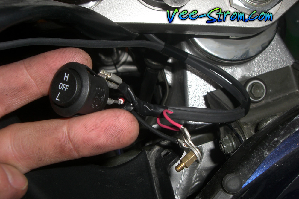
Simply, the switch needs to be accessible while riding. I chose the rocker style switch because it matches the black instrument panel plastics. The size of the switch housing is conveniently equal to the size of a US nickel. I mounted the switch on the center fuel tank cover (part 44171-06G10-291, diagram 16$) rather than the dash side panels (part 94630-27G00-291, diagram 60$) because the difference in cost to replace either piece should I ever want to undo this project is about a 40$.
Install Steps
-
Modify the horn lead wire
Transform the Suzuki horn wire into a suitable power lead. Our goal is to lengthen this power connector by a few feet. This picture illustrates how I removed the black plastic end casing, the shroud, and the crimped wire ends. I have also labeled the hot wire to distinguish it from the ground.
I enjoy wiring and soldering, so I really took my time extending this power wire. This picture shows the red ground wire that came with the Symtec kit and a black wire extending the length. I used shrink wrap and a heat gun to cover my joints and encase the wires themselves.
-
Install the heating elements
The most labor intensive part of this project is working with the rubber hand grips. I used a spray bottle of water and a few drops of dish soap to lubricate the handlebar and the hand grips. Do not use WD40 or any petroleum product on your hand grips, or they will not reseat during the reinstall. Remove both and clean the mounting surfaces with some rubbing alcohol to remove any glue residue left behind.
Insulate the left handlebar with some electrical tape to help shield the metal handlebar from drawing some of your heat. I used a heat shrink wrap instead, and my left grip is now has a lump from this wrap shrinking unevenly. The choice is yours.
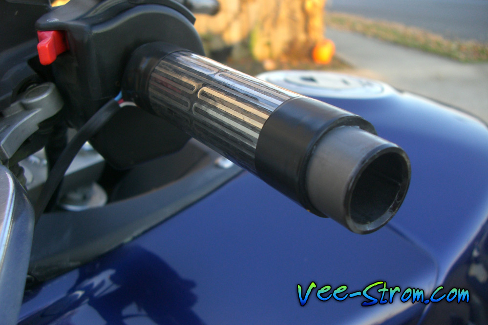
Stick the heating elements in place and wrap them with some electrical tape. Use more tape than shown in this picture. The heating elements are abused a bit when reinstalling the rubber grips, and this amount of tape will not hold them securely.
-
Route wiring
While planning this project, I was considering whether or not to open the factory wire looms that follow the handlebar to each grip. My idea was to completely conceal the new wires for a nice stealth install. I decided against this because the wires we are adding are easily hidden while following the existing wire and cable paths on the bike. I taped the new wires to the bottom of the hand control wire looms, and the power lead coming up from behind the radiator follows the path of a brake line. Everything is black, and it blends in nicely. Make sure you leave enough slack in your wiring for turning clearance. Rotate the handlebars from full left to full right to make sure the modification does not interfere with the bike’s steering.
-
Test time
Turn the key to position one and turn on the grip heaters. Make sure they work before you mount the switch and reinstall the rubber.
-
Mount the switch
The picture really tells the story here. As I mentioned earlier, the rocker switch is the same size as a nickel. I laid a nickel on the back side of this plastic piece and hit it with some spray paint really quick to create a pattern. I drilled holes around the circumference of this circle before punching out the center and smoothing the inside of the hole with sand paper.
-
Reinstall the rubber grips
After you have verified that your installation is working properly, install the grips on top of your heating elements. I used soapy water once again, but I avoided using the grips again for 24 hours to let the water dry.
It’s hard to review something like this and be critical at all—heated grips are pure win. I love projects like this, and the heat is exactly what I needed to make my Pennsylvania winter rides more enjoyable. I hope my photos help you with your own project. As always, let me know how else I can help.
Posted on January 11th, 2010 in Tutorials | 5 Comments »
